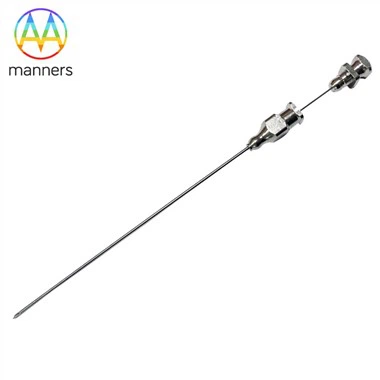
Cutting Cannula
Sep 18, 2026
Pain Point - When the Blade Fails, the Diagnosis Fails
If the stylet notch is the capture mechanism, the outer cutting cannula is the blade that seals the diagnosis. Yet across the industry, the cannula is routinely underestimated, treated as a passive tube that simply slides over the stylet. This assumption creates a cascade of clinical failures. The most common is "tissue throw" - the specimen is captured in the notch, but as the cannula fires forward at 15–20 m/s, the tissue escapes rather than shearing. Instead of a clean core, the pathologist receives a shredded fragment with crushed margins, rendering immunohistochemistry unreliable. Another failure mode is excessive insertion force: a dull or poorly shaped cannula tip requires more axial push to penetrate tissue, causing the physician to apply additional hand pressure that displaces the target lesion by several millimeters - enough to miss a small breast mass or a suspicious thyroid nodule entirely. A third failure is lumen roughness: after the cannula severs the core, the inner wall must allow the specimen to slide out smoothly into the pathology cassette. If the laser-cut surface or the electropolish is inadequate, the core drags, fragments, or leaves behind cells that contaminate the needle for the next pass. For OEMs, these failures manifest as CAPA triggers, negative physician feedback, and lost market share to competitors whose cannulae "feel sharper" - a subjective but decisive clinical differentiator.
Principle - Wedge Mechanics and Surface Science
The cutting cannula operates on wedge mechanics. As the cannula advances over the stylet, its distal tip - typically a bevel, trocar, Franseen, or SharkCore geometry - converts axial firing energy into a radial shearing force. The tissue caught in the stylet notch is pinched between the cannula's cutting edge and the stylet wall. The sharper the edge radius and the more optimized the wedge angle, the lower the shear force required, and the cleaner the cut. The governing equation for cutting force F = τ × A + μ × N describes the sum of tissue shear strength (τ) across the cross-sectional area (A) plus frictional resistance (μ) against the normal force (N). Reducing edge radius reduces N; improving surface finish reduces μ. This is where laser-cut hypotube technology becomes transformative. With a 0.012 mm kerf, manufacturers can create micro-reliefs on the cannula tip that act as micro-channels, reducing friction and lowering puncture force by 30–50% compared to a smooth-ground surface. Furthermore, gradient cutting patterns - continuous spirals for uniform flexibility, interrupted spirals for torque-plus-flex, radial cuts for rotation-limiting stops - allow the cannula to be stiff distally for cutting power while remaining flexible proximally for kink resistance during device manipulation. Material selection adds another dimension: 316L for general use, 17-7PH for high-load applications, Nitinol for steerable access, and L605 cobalt-chromium for exceptional fatigue resistance in high-cycle devices.
Equipment Classification - The Cannula Production Line
Manufacturing a high-performance cutting cannula requires: (1) Precision Bevel Grinders - Diamond-wheel or CBN grinders that form the primary cutting tip at angles from 15° to 45°, depending on tissue type. These machines achieve tip symmetry within ±2 µm, critical for preventing side-drift during insertion. (2) Laser Slitting and Cutting Systems - Fiber lasers for 304/316L cannulae, cold-laser (USP) systems for Nitinol. These create the distal cutting slots, echogenic textures, and proximal flexibility zones. The 0.012 mm kerf capability enables micro-relief patterns that reduce puncture force without compromising column strength. (3) Electropolish and Ultrasonic Cleaning Cells - Multi-stage chemical baths that remove recast layer and reduce Ra to <0.2 µm. Ultrasonic agitation ensures lumen cleanliness, preventing tissue adhesion and particulate shedding. (4) Vision Metrology and OCT Inspection - Optical coherence tomography scans the inner lumen for micro-burrs or dimensional deviations. Vision systems verify tip geometry, bevel symmetry, and cutting-edge sharpness. (5) Firing-Force Test Rigs - Simulated tissue phantoms (ballistic gel, porcine liver) instrumented with load cells to measure puncture force, cutting force, and specimen fragmentation rate under controlled firing velocity.
Practical Guide - Designing the Cannula
Step 1: Select tip geometry by tissue. Bevel tips for superficial lesions (breast, thyroid). Trocar (three-face pyramid) for dense tissue (prostate, liver). Franseen (four-point crown) for histology-rich cores requiring minimal crush. SharkCore (distal forked design) for endoscopic ultrasound (EUS) biopsies of solid pancreatic masses. Step 2: Optimize wall thickness. Balance cutting power against trauma. A thicker wall (0.06–0.08 mm for 14–16 G) resists firing recoil and maintains tip geometry. A thinner wall (0.03–0.04 mm for 20–22 G) reduces insertion force but requires tighter process control to prevent kinking. Step 3: Specify surface finish. Inner lumen Ra < 0.2 µm to prevent tissue drag. Outer surface may incorporate laser-etched echogenic texture near the tip for ultrasound visibility, provided it does not roughen the cutting edge. Step 4: Validate in tissue phantom. Fire the assembled needle 50 times into calibrated gel. Measure specimen length, fragmentation, and firing force. Acceptable fragmentation rate: <10% of core length. Firing force: within 15–25 N for 14–16 G, 5–12 N for 20–22 G. Step 5: Sterilization compatibility. Validate ethylene oxide (EO) or gamma sterilization does not degrade surface finish or alter material properties. Nitinol transformation temperature must remain within specification after sterilization.
Real-World Experience - Clinical Lessons
An EBUS-TBNA (endobronchial ultrasound transbronchial needle aspiration) cannula appeared sharp on optical inspection but consistently crushed lymph node cores in clinical use. Investigation revealed the back-cut edge radius was >5 µm, causing the tissue to compress rather than shear. Re-grinding the edge to <3 µm and adding a helical micro-groove texture for ultrasound visibility improved node visualization and produced ribbon-like cores suitable for flow cytometry. Pneumothorax incidence in the follow-up cohort dropped from 4% to 1.2%, attributed to more accurate targeting with the echogenic tip. A peripheral CNB cannula for liver biopsy suffered from tip deflection during firing, causing the core to be cut at an angle. The cannula wall was 0.04 mm in 316L, too thin for the firing recoil. Redesigning with a 0.06 mm wall and adding an interrupted-spiral proximal zone improved kink resistance without compromising trackability. Specimen adequacy rose from 78% to 95%.
Summary - The Cannula as the Blade
The cutting cannula is the blade of the biopsy system. No matter how perfectly the stylet notch captures tissue, the diagnosis is only as good as the cannula's ability to sever the core cleanly and deliver it intact to pathology. A well-engineered cannula - sharp, smooth, and structurally sound - is invisible to the physician, allowing the procedure to proceed with confidence. A poorly engineered one becomes the limiting factor in patient care.
Outlook - The Sharpened Future
Motorized CNB systems will demand cannulae capable of 50+ fires without edge degradation, driving adoption of L605 cobalt-chromium and diamond-like carbon (DLC) coatings. Disposable robotic biopsy cannulae will integrate with image-guided navigation, requiring laser-cut registration marks for real-time tracking. Hybrid laser-grind processes will co-design the kerf width, cutting bevel, and micro-relief texture in a single digital model, achieving performance levels impossible with either process alone. The cannula of 2030 will be a smart, self-sharpening component that communicates its edge status to the biopsy gun - and the gun will refuse to fire if the blade is compromised.
Trocar Tip
Pain Point - The Navigator That Wanders
In coaxial biopsy procedures, the trocar-point introducer establishes the initial access tract through skin, subcutaneous tissue, and organ capsule. If the trocar tip is asymmetric, the entire trajectory deviates. A 1 mm error at the skin surface becomes a 5 mm error at the target depth - enough to miss a small renal mass or puncture a pulmonary vessel. The pain point is that many trocar tips are produced by hand grinding, resulting in face-to-face variation that creates unbalanced lateral forces during insertion. Physicians experience this as "the needle walks off course" despite their best efforts at stabilization. In lung or pancreatic biopsies, such deviation can cause pneumothorax, hemorrhage, or seeding of the needle tract with malignant cells. For OEMs, the cost is product recalls, regulatory scrutiny, and loss of physician trust.
Principle - Centered Penetration Through Symmetry
A trocar tip converts axial push into centered penetration by distributing force across three (or more) symmetrical faces. The triangular-pyramid or dagger form splits tissue along natural fault lines, minimizing lateral displacement. The principle is that for every force vector pushing tissue sideways, an equal and opposite vector must cancel it out. This requires micron-level symmetry of face angles, edge radii, and tip length. Laser-cut hypotubes with integrated guide marks and ground facets achieve repeatable tip symmetry impossible with hand grinding alone. Materials matter: 316L for corrosion resistance in blood/urine contact, 17-7PH for stiff deep puncture, Nitinol for curved bronchoscopic paths, and L605 for repeated sterile-reprocessing scenarios where fatigue life is critical.
Equipment Classification
(1) Diamond Grinders with 5-Axis CNC - Form trocar faces at programmed angles with positional accuracy of ±1 µm. (2) Laser Etching Systems - Create depth markers and orientation lines on the trocar shaft. (3) Vision Metrology - Measure tip R-angle, face symmetry, and included angle. (4) Insertion Force Test Benches - Simulate tissue penetration in ballistic gel, measuring force to advance 50 mm.
Practical Guide
Specify tip type by anatomy: three-face pyramid for most soft-tissue access; four-face for dense capsules; dagger for vascular access. Define included angle (20–30°), tip length (2–5 mm), and face count. Validate in tissue simulant. Electropolish after grinding; never before. Keep trocar OD one gauge larger than the working stylet.
Real-World Experience
A coaxial introducer for lung biopsy caused bronchial wall abrasion. Tip faces were asymmetric by 2 µm, creating net lateral force. Re-machining to symmetric <5 µm R-angle reduced insertion force 18%. Physicians reported "it walks straight now."
Summary
The trocar tip is the navigator. A bad tip means a bad biopsy before the sample is even taken. Symmetry is not a luxury; it is a safety requirement.
Outlook
Image-registered trocar tips with embedded fiducials for CT/MRI tracking will become standard. Nitinol trocars pre-shaped for peripheral lung nodules will enable transbronchial access without trans-thoracic trauma. Echogenic pyramid textures will make trocar tips visible under all imaging modalities, reducing radiation exposure from repeated scans.