Radial Cut Tube
Sep 20, 2026
Pain point
Kinking remains one of the most insidious and dangerous failure modes in interventional medicine. Unlike a fracture that is immediately visible, a kink often manifests as a subtle, localized dent in the catheter shaft. This seemingly minor deformation can have catastrophic consequences: it narrows the inner lumen, preventing the smooth passage of balloons, stents, or embolic coils; it creates a site where platelets can aggregate, leading to thrombus formation; and it can cause the device to lock up inside a vessel, forcing the physician to abandon the procedure or, worse, convert to an open surgical emergency. The pain is most acute in large‑bore delivery systems used in abdominal aortic aneurysm (AAA) repair, transcatheter aortic valve replacement (TAVR), or neurovascular stenting, where the forces required to push bulky implants through tortuous anatomy are immense. Traditional braided or coiled shafts, while flexible, tend to collapse under axial compression, especially when navigating the aortic arch or iliac arteries. Device manufacturers are caught in a relentless zero‑sum game: they must make the shaft flexible enough to track, yet rigid enough to resist buckling under high push forces. This contradiction has led to countless redesigns, delayed clinical trials, and, in some cases, abandoned programs. The financial and reputational stakes are enormous, and the need for a robust anti‑kink solution is paramount.
Principle
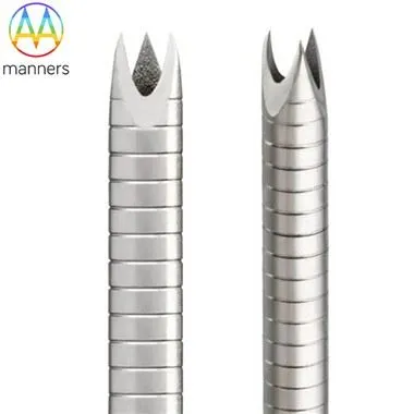
The core principle of a radial cut hypotube is to introduce circumferential structural reinforcements that resist local buckling while preserving overall flexibility. By laser‑cutting ring‑like patterns around the tube, engineers create a series of "ribs" or "corrugations" that act as hoops of support. When the shaft bends, the radial cuts allow the tube to conform to the curvature, but the uncut sections between the rings maintain the roundness of the lumen, preventing it from collapsing inward. This is analogous to the corrugated design of a vacuum cleaner hose, which remains flexible yet resists kinking under suction. The mechanics are governed by the interplay of bending stiffness and local buckling resistance: the radial pattern reduces bending stiffness only in the plane of the cut, while the uncut bridges provide circumferential integrity. For a hypotube made from 316L stainless steel or 17‑7PH, the radial cut pattern can be tuned to achieve a specific balance between flexibility and kink resistance. The minimum kerf width of 0.012 mm allows for extremely fine rings that do not significantly compromise the tube's torsional strength. When combined with other patterns, such as interrupted spirals, the radial cut hypotube becomes a versatile platform for delivering large implants through complex vascular paths.
Equipment classification
Manufacturing radial cut hypotubes requires a suite of precision equipment. At the forefront are high‑speed rotary laser cutting systems, where the tube is spun on a precision chuck while a fiber laser head moves axially to create continuous or segmented rings. For more complex geometries, five‑axis CNC laser workstations enable the cutting of variable‑pitch radial patterns that transition smoothly along the shaft length. The laser source is typically a pulsed fiber laser for stainless steel or a femtosecond laser for Nitinol, with beam delivery optics that maintain a focused spot size of less than 20 µm. Vision‑guided alignment systems ensure that each cut is placed with micron‑level accuracy, compensating for any tube ovality. Post‑processing equipment includes electropolishing tanks that remove micro‑burrs and recast layers from the cut edges, and passivation lines that enhance corrosion resistance. Finally, specialized kink‑testing rigs apply combined bending and axial compression to quantify the angle at which the lumen loses 50 % of its cross‑sectional area, providing a direct measure of clinical performance.
Practical guide
To design an effective radial cut hypotube, engineers should begin by defining the worst‑case anatomical path and the maximum push force expected during deployment. Use finite element analysis (FEA) to model the stress distribution and optimize the ring spacing, width, and transition zones. For AAA or TAVR applications, prioritize radial rings or interrupted radial patterns with 316L or 17‑7PH for high strength. Always validate the design under combined loads-bending plus axial compression plus internal fluid pressure-because real‑world conditions are multi‑axial. Single‑load tests are insufficient and often misleading. Incorporate a PTFE inner liner if the device must pass balloons or stents through the lumen, as this provides a smooth surface and prevents snagging if minor deformation occurs. After laser cutting, perform electropolishing to remove micro‑sharp edges at the ring bridges, as these can become fatigue initiation sites. Finally, document all parameters and results to support regulatory submissions, ensuring full traceability per ISO 13485.
Real‑world experience
A compelling case involved a TAVR delivery system that initially suffered from kinking during valve deployment in the aortic annulus. The original shaft was a braided polymer tube that collapsed under the high push force required to advance the crimped valve through the iliac artery. By redesigning the shaft with a radial cut hypotube featuring interrupted rings in the distal 15 mm, the manufacturer increased the kink resistance by over 50 % without sacrificing trackability. The radial rings acted as miniature hoops that prevented the lumen from collapsing, allowing the valve to be deployed smoothly. In another instance, a neurovascular stent delivery catheter used a continuous radial pattern to maintain lumen patency while navigating the tight curves of the intracranial vessels. The radial cuts distributed the compressive forces along the uncut sections, reducing the risk of thrombus formation and improving the overall safety of the procedure. These examples underscore that radial cut technology is not a luxury but a necessity for high‑risk interventions.
Conclusion
The radial cut hypotube represents a pinnacle of laser‑fabricated medical devices, addressing one of the most critical failure modes in minimally invasive therapy. Its ability to combine flexibility with exceptional kink resistance makes it an indispensable component in large‑bore delivery systems. For a medical needle manufacturer, mastering the radial cut is a mark of engineering maturity and a direct contribution to patient safety. A well‑designed radial pattern is the silent guardian that ensures the device performs as intended, even in the most challenging anatomies.
Outlook
The future of radial cut hypotubes will likely see the integration of active materials that can change their stiffness in response to physiological cues. Imagine a radial pattern made from a shape‑memory polymer that stiffens under compressive load, providing on‑demand kink protection. Additionally, advances in 3D laser printing may enable the creation of radial cuts with varying depths, further optimizing the mechanical properties. As procedures become more complex and personalized, the radial cut hypotube will continue to evolve, driven by the relentless pursuit of safer, more effective interventional devices.