Spiral Cut Shaft
Sep 19, 2026
Pain point
Catheter shafts have historically suffered from a zero‑sum trade‑off: they must either push well or bend well, but rarely both. A solid hypotube transmits torque efficiently, allowing the physician to rotate the device and feel resistance, yet its inherent stiffness fights the anatomy, causing vessel trauma or inability to reach distal lesions. Braided or coiled shafts offer flexibility but suffer from "wind‑up"-a loss of 1:1 torque response-making precise positioning difficult. Device makers often attempt to fix this with polymer jacketing, but the underlying metal problem remains: the shaft lacks a tunable mechanical gradient. Months are wasted iterating sheath materials while the core tube's performance ceiling stays unchanged. The pain intensifies as procedures move to more tortuous anatomies like the posterior descending artery or the small vessels of the brain, where a shaft that is too stiff can cause dissection and one that is too floppy cannot be advanced.
Principle
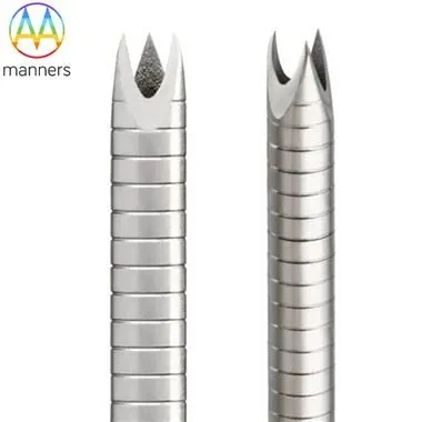
A spiral‑cut hypotube resolves this by removing material in a helical pattern along the shaft. The pitch of the spiral dictates flexibility: a tight pitch increases the number of cuts per unit length, enhancing compliance; a wide pitch retains more metal, preserving stiffness. Continuous spiral cuts provide uniform bending in all directions, while uncut helical bridges maintain torsional continuity. Thus, the physician's hand rotation travels down the shaft because enough metal remains between slits to carry shear stress. The tube becomes a "programmable spring," with flexibility and torque balanced by design rather than material substitution. The laser‑cut pattern essentially creates a series of micro‑hinges that allow the shaft to bend in a controlled radius while still transmitting rotational force.
Equipment classification
- Continuous spiral hypotube: uniform flex, low‑load navigation for urinary or peripheral scopes. Ideal for diagnostic catheters where torque is less critical.
- Interrupted spiral hypotube: spiral cuts interspersed with solid bridges, offering superior kink resistance for PTCA balloon or stent delivery. The bridges act as anti‑buckling ribs.
- Variable‑pitch spiral: stiff proximally, flexible distally, ideal for navigating from femoral access to coronary arteries. The pitch transitions smoothly or in steps.
- Multi‑start spiral: two or more intertwined helices creating complex bend planes for steerable devices. Allows for bidirectional bending without twisting the entire shaft.
- Spiral‑radial hybrid: combines flex zones with articulating joint zones for advanced endoscopic tools. The spiral section provides gentle curves, while radial cuts create discrete joints for sharp articulation.
Practical guide
Use continuous spiral for applications where gentle navigation matters more than push force, such as ureteroscopy or diagnostic angiography.
Choose interrupted spiral for high‑pressure delivery systems where kink failure is unacceptable, like coronary stenting or thrombectomy.
Avoid a single pitch for the entire shaft unless the anatomy is straight; instead, segment the pattern into 3–4 zones based on FEA‑predicted stress distribution.
Tune laser parameters to the alloy: Nitinol requires lower power and higher pulse frequency to minimize HAZ compared to 304 stainless.
After cutting, electropolish to remove recast and improve lubricity; validate torque transmission and bend radius at each zone transition using a torque‑response test rig.
Consider adding a polymer jacket (e.g., PEBAX or nylon) over the spiral cut shaft to reduce friction and improve trackability, but ensure the jacket does not fill the cuts and negate flexibility.
Real‑world experience
Engineers frequently over‑cut the distal end to "make it floppy," only to find the tip folds under push force during simulated use. Conversely, retaining too much metal proximally makes the shaft too stiff to enter a tortuous vessel. The best neurovascular shafts we've produced use 3–4 pitch zones, with transition lengths calculated via FEA. In one project, adjusting the spiral pitch from 0.5 mm to 0.8 mm in the mid‑shaft reduced insertion force by 30 % without compromising torque response. Another case involved a carotid stent delivery system that suffered from "whipping" during rapid rotation. Switching from a continuous spiral to an interrupted spiral with 2 mm solid bridges every 10 mm eliminated the whipping and improved stent deployment accuracy.
Conclusion
Spiral‑cut shafts transform a simple tube into a tuned mechanical spring. The pattern-not the alloy alone-determines whether the device feels "alive" in the physician's hand, enabling atraumatic access and precise therapy delivery. For a medical needle manufacturer, mastering spiral‑cut design is a core competency that directly impacts clinical outcomes.
Outlook
As robotic catheterization and steerable electrophysiology ablation advance, spiral patterns will be generated via closed‑loop algorithms: simulation → laser cut → fatigue data → automatic pattern revision. This will yield patient‑specific shafts with embedded sensors for real‑time force feedback, pushing the boundaries of what is possible in minimally invasive therapy.