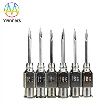
Selecting Conical Dispensing Needles By Inner Diameter
Nov 12, 2026
1 Pain Points
The most common question in a dispensing project is also the least well answered: which inner diameter should be used? Catalogues present a ladder of sizes, engineers are often advised to "start small and open up if needed", and the result is a drawer full of partially used nozzles and a process that was never properly characterised.
Choosing the wrong bore has consequences in both directions. Too small, and the system must generate high pressure to move the adhesive, which compresses the material, produces a surge when the valve opens, and encourages phase separation in filled products. Too large, and the deposit cannot be controlled at short cycle times: the adhesive flows by gravity, drips between shots, and forms a tail that either lands on the part or contaminates the fixture.
Filled and thixotropic adhesives add another dimension. A bore that is comfortable for an unfilled cyanoacrylate can be marginal for a silver-filled epoxy, because the largest particles in the filler must pass the narrowest section without bridging. The restriction is not only the bore at the tip but the whole converging path.
The cost of getting this wrong appears as variation rather than as a single dramatic failure, which is why bore selection is worth treating as an engineering decision with a documented rationale rather than a trial-and-error exercise.
2 Working Principle
Flow through a circular channel is governed by a relationship in which volumetric flow increases with pressure and with the fourth power of diameter, while decreasing with length and viscosity. The fourth-power dependence is the reason bore selection dominates dispensing behaviour: a small reduction in diameter reduces flow far more than a proportional change in pressure or time would suggest.
In a conical nozzle, the channel is not uniform. The inlet is comparatively wide and the section narrows continuously to the orifice. Most of the pressure drop therefore occurs in the final portion, and the overall resistance is lower than that of a straight cannula of the same exit diameter and comparable length. This is the practical advantage of the taper: a given orifice size can be operated at a lower pressure, which reduces compression of the adhesive and shortens the settling time after the valve closes.
Thin-wall construction extends the same logic outward. A thin wall at the tip allows the outer diameter to stay small while the bore remains larger than a thick-walled cannula of the same outer size would permit. In recessed or densely populated assemblies, this is the difference between reaching the target area and fouling adjacent parts.
Viscosity and shear behaviour complete the picture. Many adhesives are shear-thinning, so their apparent viscosity falls as flow rate rises. A nozzle that is too restrictive forces the material into a high-shear regime at the tip, which can produce a thin, fast-moving stream rather than a controlled dot. A slightly larger bore with a well-controlled pressure profile usually gives a more stable deposit.
3 Equipment Classification
Inner diameter is usually organised as a ladder from 0.1 mm to 0.8 mm, with intermediate sizes chosen to bracket typical deposits. The practical meaning of the ladder differs by application.
The smallest sizes, roughly 0.1 mm to 0.2 mm, are used for micro-dots, fine lines and low-viscosity fluids such as UV-curable adhesives and thin cyanoacrylates. At this scale, filtration of the adhesive and cleanliness of the connection become critical, because a particle of a few tens of micrometres is a significant fraction of the bore.
Mid-range sizes, approximately 0.25 mm to 0.4 mm, cover the majority of electronics and medical assembly work: dots for component bonding, small encapsulations, and short beads for sealing. This range tolerates modest filler content and is generally the first choice when a process must be both precise and robust.
Larger sizes, 0.5 mm to 0.8 mm, suit higher-viscosity materials, filled epoxies, larger beads and faster cycle times. They are also used where the deposit size is set by the application rather than by miniaturisation, for example gasket beads or potting of small modules.
Beyond the standard ladder, custom diameters and taper angles can be produced to drawing. This is relevant when a proprietary valve has an unusual outlet, when the deposit requires a taper that no standard part provides, or when a thicker wall is needed for mechanical strength in a demanding fixture.
Nozzle families also differ in tip profile: sharp conical points for access, blunt tips for surface contact, and chamfered tips that resist damage. Coated versions with nickel-PTFE are selected where adhesive adhesion inside the channel is a maintenance issue, while PTFE-enriched materials provide an inert alternative for particularly aggressive chemistries.
4 Practical Guide
A structured selection method avoids most of the guesswork.
First, quantify the deposit. Measure the required dot diameter or line width and the acceptable volume tolerance. As a working rule, a dot diameter close to the inner diameter, or slightly larger, indicates a reasonable match for low-viscosity fluids; a dot much larger than the bore suggests excessive pressure or dwell.
Second, screen by particle size. Identify the largest filler particle in the adhesive and choose a bore at least several times that dimension. Where the data sheet is silent, a simple filter test, passing the adhesive through a mesh of known opening, gives an indication of the practical particle ceiling.
Third, consider viscosity and cycle time together. A high-viscosity material at a short cycle time needs a larger bore or a positive-displacement system; a low-viscosity material at a short cycle time needs a smaller bore and reliable suck-back to prevent dripping.
Fourth, evaluate the tip profile against the part. If the nozzle must enter a cavity, check clearance using the outer diameter, not the bore. If the tip contacts the surface, a blunt or chamfered profile distributes force and resists deformation.
Fifth, confirm supply and documentation. Standard cartons are adequate for most production use; where handling is automated, ask for packaging that presents nozzles in a fixed orientation. For custom parts, retain the drawing revision and the sample that was approved, and confirm that the supplier works to a recognised quality system such as ISO13485 when the end product is a medical device.
Finally, validate on real parts. Dispense a run of at least thirty deposits, measure them, and confirm that the distribution sits comfortably inside tolerance rather than at its edge. Only then release the process.
5 Field Experience
Several observations recur when bore selection is reviewed after the fact.
The most frequent error is choosing a bore that is too small, because a small bore feels more precise. In reality, the smallest usable bore is the one that allows the required deposit at a comfortable pressure with a clean shot ending. Going smaller than that tends to increase variation rather than reduce it.
The second most frequent error is neglecting the whole fluid path. A nozzle with a 0.15 mm bore connected to a barrel with a much larger outlet, a long adapter and a coarse filter will still exhibit interruptions, because particles and air collect upstream. Matching the nozzle to a clean, short path is as important as the bore itself.
Operators often compensate for a marginal bore by increasing pressure. This produces a fast, uncontrolled shot with a tail, and the tail is frequently the source of contamination complaints. Reducing pressure and increasing dwell, or moving one step up in bore, usually resolves the problem more cleanly.
Where filled adhesives are used, lot-to-lot variation in filler distribution can make a bore that worked last month marginal this month. Keeping a slightly larger spare size available avoids line stoppages during such transitions.
Finally, documentation pays. Teams that record bore size, lot, pressure, time and standoff for each product find that new products can be brought up quickly, and that recurring issues are recognised as process drift rather than as random faults.
6 Summary
Inner diameter is the single most influential parameter in conical nozzle selection, because flow depends so strongly on it. A tapered channel reduces the pressure needed for a given orifice, thin walls allow access without sacrificing bore, and the Luer lock interface keeps the assembly concentric and leak-free. Selecting the bore is best done from the deposit backwards: define the volume, screen for particle size, consider viscosity and cycle time, check clearance, then validate on real parts. Treated this way, bore selection becomes a documented engineering decision instead of a sequence of trials.
7 Outlook and Recommendations
As deposits shrink, the small end of the diameter ladder will matter more, and dimensional consistency at 0.1 mm to 0.2 mm will become a purchasing criterion rather than a detail. At the same time, the growth of filled and highly reactive adhesives will push demand for coated and PTFE-enriched flow paths that resist adhesion and cleaning damage.
For engineering teams, three recommendations follow. Maintain a small, curated set of bore sizes rather than a large drawer of options, and document the rationale for each. Qualify a customisation route early, using 2D or 3D drawings or a sample, so that an unusual requirement does not become a schedule risk. And involve the supplier in the selection process: a manufacturer working to ISO13485 can advise on taper geometry, wall thickness and coating options, and can supply the dimensional records that regulated customers need. Good bore selection is not a matter of intuition; it is a short, disciplined analysis that saves months of production tuning.