Hybrid‑Structure Braided Hypotube: Combining Braid Reinforcement With Laser‑Cut Patterned Base Tube
Sep 03, 2026
Pain Points
Pure full‑length braided hypotube gains excellent radial crush resistance, yet the braid layer raises overall shaft stiffness, making it hard to achieve ultra‑soft distal performance for navigating delicate cerebral and peripheral vessels. Pure laser‑cut hypotube delivers tunable flexibility‑torque balance via spiral, radial or bespoke cut patterns, but suffers insufficient radial crush‑resistance under external squeezing force. Medical device OEMs face a dilemma: distal segments need ultra‑high pliability for atraumatic vessel tracking, while middle‑proximal sections demand robust anti‑crush capacity plus torque‑push performance. Simple mechanical assembly of separate braided segment and laser‑cut segment creates physical joints, introducing potential fracture points and increasing assembly complexity. Designers expect monolithic hybrid‑structure braided hypotube: partial‑length braid reinforcement over laser‑cut base hypotube, to realize segmented differentiated mechanical properties. Base‑tube processing scope covers Ø0.20 mm‑20 mm tubing with minimum 0.012 mm kerf width under ISO9001:2015 and ISO13485 quality standards. Custom hybrid‑structure configuration can be built according to customer 2D/3D drawings or physical samples for cardiovascular, abdominal aortic aneurysm and urinary interventional devices.
Working Principle
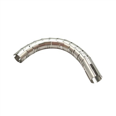
Hybrid‑structure braided hypotube adopts monolithic laser‑cut metallic hypotube as base substrate. Partial axial sections of this base tube receive braid‑wire reinforcement, while other sections keep bare laser‑cut surface without braid covering. Base‑tube material includes 304, 316L stainless steel, 17‑7PH, Nitinol and L605. Laser‑cut patterns on base tube include continuous spiral cut, interrupted spiral cut, radial cut and bespoke custom cuts, with minimum kerf width 0.012 mm within Ø0.20 mm‑20 mm dimension range. Braid‑reinforced segments obtain greatly improved radial crush‑resistance, retaining pushability and torque transmission from base hypotube. Bare laser‑cut segments preserve high bending flexibility determined by laser‑cut geometry. Engineers define braid‑coverage length, braid‑parameter settings, and laser‑cut pattern layout on different axial zones. Proximal‑middle sections can apply braid reinforcement for anti‑crush requirement; distal tip remains bare laser‑cut structure for maximum softness. Transition zones exist between braid‑covered area and bare‑tube area; stress‑concentration risk arises at this boundary, so gradual‑transition design is required. The whole component is built on one single base‑tube substrate, avoiding multi‑part assembly joints.
Equipment Classification
Three core equipment sets support hybrid‑structure braided hypotube manufacturing. First, precision laser‑cutting workstations: fabricate monolithic base hypotube with multi‑zone varied laser‑cut patterns according to customer 2D/3D drawings or physical samples, processing tubing Ø0.20 mm‑20 mm with minimum kerf width 0.012 mm. Second, programmable partial‑coverage tubular braiding machines: realize segmented braid weaving on designated axial zones of pre‑fabricated laser‑cut base hypotube, supporting stainless‑steel, Nitinol and L605 braid wires. Third, post‑processing and comprehensive‑validation equipment: termination‑fixing stations, deburring‑passivation units, and multi‑function mechanical‑test benches for crush‑resistance, torsion, push‑load, kink‑resistance and cyclic‑fatigue testing. All production procedures comply with ISO9001:2015 and ISO13485 medical‑quality‑system requirements. Raw‑material incoming inspection validates base‑tube and braid‑wire metallurgical and dimensional quality. Finished goods can adopt standard carton or customer‑specified packaging.
Practical Operation Guidelines
Define clinical segmentation requirements: confirm which axial zones need braid‑reinforced anti‑crush performance and which zones require bare laser‑cut high flexibility. Select base‑tube alloy material. Design multi‑zone laser‑cut pattern layout for base hypotube, specify kerf width ≥0.012 mm. Define braid‑coverage range, braid‑wire material, picks‑per‑inch, braid angle and wire‑diameter for braid‑reinforced zones. Optimize transition‑zone geometry between braid‑covered and bare‑tube sections to mitigate stress concentration. Submit 2D/3D drawing or physical sample for manufacturability review. Fabricate laser‑cut monolithic base hypotube first. Then perform segmented partial‑coverage braiding and corresponding termination‑end fixation. Manufacture hybrid‑structure prototype samples. Conduct multi‑zone mechanical‑performance testing: radial crush test for braid‑reinforced zone, flexibility‑bending test for bare laser‑cut zone, full‑length torque‑push test and cyclic‑fatigue test focusing on braid‑bare transition boundary. Adjust laser‑cut pattern or braid parameters if performance fails target. Complete deburring, cleaning and passivation post‑processing. Carry out full dimensional and surface‑quality inspection. Adopt standard carton or customer‑specified packaging. Archive complete ISO‑compliant batch traceability documentation.
Practical Industry Experience
Production practice shows hybrid‑structure design perfectly solves the contradiction between anti‑crush requirement and distal ultra‑soft requirement. The transition boundary between braid‑covered segment and bare laser‑cut segment is high‑stress hot‑spot; abrupt boundary layout easily induces fatigue crack under cyclic deformation. Many prototypes failed because engineers set braid‑bare transition right above dense laser‑cut kerf positions. When braiding onto pre‑laser‑cut base hypotube, excessive braiding tension may deform delicate laser‑cut slits; braiding‑machine tension parameter must be strictly controlled. Simulation analysis must take both braid mesh and laser‑cut notch stress effect into consideration. Physical prototype multi‑zone mechanical testing cannot be replaced by pure simulation. Engineering drawings should clearly mark braid‑coverage range and multi‑zone laser‑cut parameters.
Summary
Hybrid‑structure braided hypotube integrates partial‑length braid reinforcement and multi‑zone laser‑cut patterned monolithic base tube. It achieves segmented differentiated mechanical performance: braid‑reinforced zones deliver robust radial crush‑resistance; bare laser‑cut zones retain high bending flexibility. Reasonable transition‑zone design avoids stress‑concentration risk at braid‑bare boundaries. This monolithic hybrid solution eliminates reliability hazards brought by multi‑component assembly joints for minimally‑invasive interventional delivery systems.
Outlook & Suggestions
Future technical trend explores finer segmented‑braid technology for micro‑hybrid hypotube below Ø0.3 mm for micro‑catheter systems. Designers should further optimize transition‑zone geometry algorithm for braid‑bare boundary. Manufacturers need to improve low‑tension braiding‑process for pre‑laser‑cut delicate base hypotube. Quality verification shall strengthen cyclic‑fatigue assessment targeting transition zones, to meet growing clinical demands of neurology and complex peripheral‑vascular interventional operations.