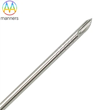
Fatigue‑Failure Risk Control For Braided Hypotube In Long‑Duration Minimally‑Invasive Procedures
Sep 03, 2026
Pain Points
Braided hypotube bears combined cyclic load of bending, torsion, radial compression and tensile force during clinical interventional operations. Multiple potential fatigue‑crack initiation sites exist: braid‑wire crossover points, braid termination ends, braid‑bare transition boundaries and laser‑cut kerf roots on base hypotube. After repeated cyclic deformation, micro‑cracks nucleate at these high‑stress locations, expand gradually and finally cause braid‑wire breakage or base‑tube fracture. Such fatigue failure brings serious safety risks for cardiovascular, abdominal aortic aneurysm, neurology and urinary interventional devices. Many development teams only execute static mechanical tests including crush‑resistance and torque measurement, ignoring cyclic‑fatigue validation. Even static indexes meet specification, components may fail under dynamic cyclic service condition. When switching base‑tube alloy, braid‑wire material or braid‑structure parameters, many engineers reuse old‑project experience without re‑evaluating fatigue life. Fatigue‑failure events delay medical‑device project progress and increase R&D costs. Braided hypotube base tube can be laser‑processed within Ø0.20 mm‑20 mm scope with minimum 0.012 mm kerf width, manufactured complying with ISO9001:2015 and ISO13485 standards. Custom structures can be realized from customer 2D/3D drawings or physical samples.
Working Principle
Braided hypotube is constructed by weaving metallic braid mesh onto base hypotube substrate. Base‑tube materials include 304, 316L stainless steel, 17‑7PH, Nitinol and L605; base tube may carry laser‑cut patterns such as continuous spiral, interrupted spiral and radial cuts with minimum kerf width 0.012 mm. Under cyclic bending‑torsion‑crush combined load, relative sliding and friction occur between crossed braid wires, generating local stress at crossover nodes. Braid termination ends and braid‑bare transition zones create geometric discontinuity and stress concentration. If base tube is laser‑cut, kerf‑root notches act as inherent fatigue‑crack sources. Base‑tube alloy property, braid‑wire material, braid geometric parameters, termination‑end structure, transition‑zone design and surface finishing status jointly determine overall fatigue life. L605 cobalt‑chromium material possesses excellent intrinsic cyclic‑fatigue resistance. Nitinol can realize long‑life performance under proper process control. Sharp edges and unpolished surfaces will amplify notch effect and shorten fatigue service cycles. Optimized structure design, reasonable material selection and high‑quality post‑processing can mitigate fatigue‑failure risk.
Equipment Classification
Three major equipment groups support braided hypotube fatigue‑risk control. First, braiding and laser‑cutting manufacturing platforms: produce braided hypotube and patterned base substrates according to customer 2D/3D drawings or samples, precisely control geometric features to avoid excessive stress‑raising notches. Second, dedicated post‑processing equipment: termination‑fixing stations, deburring and passivation units to remove sharp edges and smooth high‑stress locations. Third, multi‑mode cyclic‑fatigue‑test benches: simulate clinical combined bending‑torsion‑crush cyclic load to assess component service life. Whole‑set production follows ISO9001:2015 and ISO13485 medical‑quality‑management‑system requirements. Raw‑material incoming inspection checks metallurgical quality, because material internal defects will also become fatigue‑crack starting points. Finished‑product packaging supports standard carton or customer‑specified requirements.
Practical Operation Guidelines
Define clinical cyclic‑loading boundary conditions: maximum bending radius, radial crush‑load amplitude, rotation angle and expected service cycle counts. Select base‑tube and braid‑wire alloy: choose L605 combination for ultra‑high‑cycle‑fatigue requirement; adopt Nitinol when superelasticity plus fatigue‑resistance are needed; select stainless‑steel grades for general‑load scenarios. Design braid‑structure, termination‑end layout and transition‑zone geometry; avoid abrupt geometric mutation which will generate stress hot‑spots. If base tube uses laser‑cut patterns, set kerf width no less than 0.012 mm and optimize kerf‑root surface quality. Submit 2D/3D drawing or physical sample for manufacturability review. Fabricate prototype samples. Execute static‑performance tests (crush‑resistance, torque, pushability, kink‑resistance), then carry out combined‑mode cyclic‑fatigue test. If fatigue life fails target value, modify braid parameters, optimize termination‑transition structure or adjust material selection. Complete braiding, termination processing, deburring and passivation cleaning. Perform dimensional and surface‑quality inspection. Adopt standard carton or customer‑specified packaging. Retain complete ISO‑compliant batch traceability documentation.
Practical Industry Experience
Practical manufacturing feedback shows most braided hypotube fatigue failures happen at braid‑wire crossover points, termination ends or braid‑bare transition boundaries, rather than uniform main‑body material fracture. Even high‑quality raw alloy will suffer early‑stage fatigue damage if geometric discontinuity and sharp notches are not eliminated. Static‑test results cannot represent dynamic cyclic‑fatigue behavior; many prototypes pass static evaluation yet fail quickly under repeated load. Simulation stress analysis must include geometric notch effect instead of adopting ideal smooth‑geometry model. Fatigue‑test load parameters should mimic real clinical movement amplitude instead of applying arbitrary loading magnitude. Engineering drawings must specify termination‑end and transition‑zone requirements, not only outer dimension and braid‑density parameters.
Summary
Fatigue crack at braid crossover nodes, termination ends, transition boundaries and laser‑cut kerf‑roots represents key failure mode for braided hypotube under multi‑factor cyclic load. Fatigue performance depends on alloy material selection, braid‑structure geometry, termination‑transition design and surface‑finishing quality. Combined static‑plus‑cyclic‑fatigue validation and proper post‑processing effectively reduce fracture risk. Fatigue assessment is an indispensable development link for braided‑hypotube‑based minimally‑invasive interventional devices.
Outlook & Suggestions
Future R&D direction develops low‑stress‑concentration braid‑crossover geometry for ultra‑small‑diameter braided hypotube below Ø0.3 mm. Device developers should add fatigue‑life index into early‑stage design specification. Manufacturers need to further upgrade termination‑and‑transition‑zone processing technology for Nitinol braided hypotube. Quality‑control teams should establish standardized combined‑mode cyclic‑fatigue‑test workflow, to satisfy higher safety requirements of next‑generation neurology and complex multi‑site vascular interventional instruments.