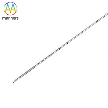
Flared Catheter Tubes: Why The 2.25-Inch Inlet Decides Performance
Nov 06, 2026
1. The Pain Point: Everything Works on Paper and Nothing Works in Service
A suction line is usually specified by flow rate and pump curve. The tube is then chosen to match the pump connection and the job is considered done. Weeks later the pump cavitates, the tip chatters, product foams, and the operator blames the pump.
The real problem sits at the inlet. A flared catheter tube with a 2.25" suction head inlet, a 2.25" nozzle outlet and an 11-inch tip is a short, stiff, high-velocity component. Its inlet is not a passive hole; it is a flow-control feature. The bell radius, the flare angle, the surface finish and the concentricity of the bell to the bore all influence how evenly fluid enters. Get them wrong and the tube delivers exactly the pressure drop the pump cannot tolerate.
Field complaints rarely point at the inlet, because the symptom appears downstream. Cavitation noise is heard at the pump. Vibration is felt in the pipework. Foam appears in the tank. The inlet of the catheter tube simply sits there, looking correct, while quietly generating the swirl and separation that cause all three.
This article explains how inlet geometry converts into hydraulic performance, which equipment and tube variants change that performance, and how to specify and verify an inlet that behaves.
2. The Working Principle: The Bell Is a Diffuser in Reverse
A bell-mouth inlet works by presenting the fluid with a gradual contraction instead of an abrupt one. When liquid turns a sharp 90° corner into a bore, it separates. A vena contracta forms just inside the entrance, the effective flow area shrinks, and the pressure drop rises far above what a simple friction calculation predicts. For a 2.25" bore running at typical transfer velocities, an abrupt inlet can cost several times the loss of a well-formed bell.
The flare solves this by making the entrance radiused. Flow accelerates smoothly along the bell surface, the boundary layer stays attached, and the contraction coefficient approaches unity.
Two secondary effects matter. First, a bell inlet reduces pre-swirl. Swirl entering a pump increases axial thrust and can push a pump toward cavitation at lower suction pressures than the datasheet suggests. Second, a concentric bell equalises velocity around the circumference, which keeps the 11-inch tip from being deflected by asymmetric loading.
The flare also participates in the mechanical joint. The same cone that guides flow provides the sealing face. That dual role creates a compromise: a smoother, larger bell improves hydraulics but thins the wall at the transition and softens the sealing surface. Understanding that trade-off is the core of design.
Wall thinning follows from geometry. Expanding a 2.25" tube to a bell mouth requires the material to stretch, and the stretch concentrates at the throat. For 304 stainless, a well-controlled roller flare can hold thinning under roughly ten percent; a hammer-formed flare on the same tube may exceed twenty-five percent, which produces a hard, thin ring exactly where vibration stress peaks.
3. Classification: The Geometry Families You Will Meet
Flared catheter tubes are not one product. They fall into recognisable families, each with a different hydraulic and mechanical signature.
Straight cone flare. The classic 37° or 45° cone. Best sealing reliability, minimal flow benefit: it is a joint, not a diffuser. Standard for pressure lines and instrumentation.
Bell-mouth flare. A curved entry that expands from the bore to the full inlet diameter. This is the configuration described by a 2.25" inlet feeding a 2.25" outlet with a round tip: bore and inlet nominally equal, so the bell is a short radius rather than a large reducer. Excellent anti-cavitation behaviour, tolerant of slight misalignment in the approach piping.
Reducer flare. Inlet larger than bore, forming a genuine contraction. Useful when the approach piping is oversized, but sensitive to the transition angle; too abrupt and separation returns.
Long-tip suction nozzle. The 11-inch tip length is a lever. It positions the inlet away from the tank floor and away from wall effects, which improves draw-down behaviour and reduces vortexing. The length also raises bending moment at the flare, so tip attachment style becomes a structural question, not just a convenience.
Tip attachment variants. Clip-style attachment allows fast removal for cleaning and is common in hygienic service. Threaded attachment gives higher preload and better resistance to pressure cycling. Welded attachment is permanent and strongest but eliminates cleanability. Each shifts how much of the sealing duty falls on the flare face.
Material and finish variants. 304 stainless is the general-purpose choice: good corrosion resistance, food-safe when passivated, predictable forming. Brass and aluminium alloy serve lower-duty or weight-sensitive applications. Surface treatment ranges from pickling and passivation to polishing and brushing; inside a bell mouth, polished surfaces delay fouling and make cleaning verification easier, while anodising or powder coating must stop short of the sealing face.
Machining options that shape the inlet. Turning sets concentricity. Swaging forms the transition. Flaring forms the seal. Slot-cutting and drilling create strainers or distribution features. Each operation must respect the same datum, or the bell will be eccentric to the bore and the hydraulic advantage disappears.
4. Practical Guide: Specifying and Verifying an Inlet
Define the duty, not just the diameter. State flow rate, fluid, temperature, solids content and whether the line runs under suction or pressure. A 2.25" inlet handling clean water behaves differently from the same inlet handling a viscous product or a slurry.
Specify the transition radius. A bell radius of roughly one-quarter to one-half the bore diameter is a sensible starting point. Tighter radii save length; generous radii save pump margin.
Control concentricity and roundness. Specify total indicator runout between the bell and the bore, and roundness at the throat. These two numbers predict vibration more reliably than wall thickness does.
Match flare angle to seat angle. Never allow a 45° flare into a 37° seat, or the reverse. Include the seat angle on the purchase drawing so the two cannot drift apart between suppliers.
State allowable wall thinning. Express it as a percentage of nominal at the transition, and require a sectioned sample at first article. This single clause prevents most fatigue failures.
Verify with a flow test when the duty is critical. A simple bench test comparing pressure drop across the tube against a straight-length reference will expose a badly formed bell immediately.
Protect the sealing face through logistics. Cap both ends. A bell mouth that has been used as a handhold during packing will never seal properly.
5. Field Experience
A dairy plant replaced pumps three times on a transfer line before anyone examined the suction nozzle. The inlet was a crude 45° flare with a sharp lip, and the pump was running close to its NPSH limit. Replacing the flare with a radiused bell of the same 2.25" diameter removed the cavitation noise without touching the pump.
In a plating line, an 11-inch tip on a clip-mounted nozzle oscillated at a frequency that matched a structural resonance in the tank frame. The flare itself was sound, but the clip allowed a small amount of rocking. Adding a secondary support collar a few inches up the tip changed the natural frequency and ended the fatigue cracking at the throat.
A third case was purely dimensional: the bell was concentric with the bore but the tube as a whole was bowed. The tip entered the tank at an angle, the inlet drew preferentially from one side, and the tank developed a persistent vortex that pulled air. Straightening the tube and re-flaring restored performance. The lesson is that inlet quality is a whole-part property, not a feature of the end.
6. Summary
The inlet of a flared catheter tube is a hydraulic component disguised as a fitting. Bell geometry, concentricity, wall integrity and attachment style together determine whether a pump sees clean, uniform, low-loss flow or a swirl of separated eddies. The 2.25" inlet and outlet with an 11-inch tip is a well-balanced configuration when the flare is formed with control and the bell is concentric to the bore.
7. Outlook and Recommendations
Expect tighter integration between hydraulic design and forming design. Computational flow studies of bell profiles are already cheap enough to run per project, and the results increasingly translate into die geometry rather than hand-finished parts. On the production side, in-process measurement of throat roundness is the most valuable next investment.
For specifiers, the recommendation is to put numbers on the inlet: radius, runout, roundness, allowable thinning, and the seat angle it must match. For producers, treat the bell as a performance feature and inspect it as such. A tube that seals but chokes the pump is still a failed part.