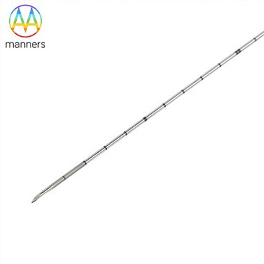
Flared Catheter Tubes: Diagnosing Eight Repeat Failures
Nov 06, 2026
1. The Pain Point: The Same Leak Keeps Coming Back
There is a particular frustration in maintenance work that comes from a fault which is fixed but not solved. A flared catheter tube leaks, the tube is replaced, the line runs, and three months later the new tube leaks in the same place.
Repeat failures are diagnostic gold, and they are usually treated as bad luck. When the same joint fails twice, the probability that the tube was defective twice is low. What is high is the probability that something in the system - the seat, the clip, the alignment, the process - is damaging every tube that is installed.
For a 2.25" stainless suction nozzle with an 11-inch tip, the number of plausible causes is manageable. There are maybe a dozen distinct failure mechanisms, and each leaves a recognisable signature. The problem is that nobody looks at the signature; they look at the leak.
This article sets out a diagnostic approach: how the failure signature is formed, what families of failure exist, and how to run an investigation that produces a cause rather than a replacement order.
2. The Working Principle: Read the Fracture, Not the Puddle
Every failure leaves evidence, and the evidence is located where the damage started, not where the fluid escaped.
Three signatures cover most cases.
Contact pattern. The wear or fretting mark on the flare face shows how much of the face was actually sealing. A full, even ring indicates good geometry and points the investigation elsewhere, toward pressure or material. A narrow ring at the outer edge indicates an angle mismatch. Two opposed arcs indicate ovality or a skewed cut. A ring at the inner edge indicates over-torque or a seat that is worn concave.
Fracture surface. A fatigue crack shows beach marks and a smooth propagation zone ending in a rough final rupture. Initiation is almost always at the throat, on the outside diameter, where thinning and bending stress peak. A single rough, granular break with no propagation zone is overload - usually a pressure surge or mechanical impact.
Corrosion morphology. Pitting concentrated in the crevice between flare and seat indicates stagnation and chloride concentration. Uniform staining along a band suggests a sensitised zone from welding. Rust streaks originating away from the seal point to free iron contamination.
A fourth, indirect signature is timing. Failure after days suggests an assembly or geometry error. Failure after months suggests fatigue, corrosion or relaxation. Failure after a specific event - a cleaning cycle, a pressure spike, a maintenance overhaul - points to that event.
3. Classification: The Failure Families
Geometry failures. Angle mismatch between flare and seat; flare diameter undersize or oversize; skewed or elliptical flare from a bad cut; incorrect seat cone wear. Signature: uneven contact ring, leak from first pressurisation.
Wall integrity failures. Excessive thinning at the throat; pre-existing cracks from a hard tube; fold lines from flaring without deburring. Signature: fatigue crack initiating at the outside of the throat.
Assembly failures. Under-torque or over-torque on threaded joints; clip not fully engaged; misalignment forcing the tube to seal at an angle; missing support allowing vibration. Signature: fretting marks, loosened fasteners, wear at one side of the face.
Material failures. Wrong grade substitution; sensitisation from welding; free iron contamination; dezincification in brass. Signature: localised corrosion not explained by the fluid.
Service-condition failures. Pressure or water-hammer surges above design; thermal cycling beyond the joint's tolerance; abrasive or corrosive fluid attacking the bore; vibration from a nearby pump or agitator. Signature: overload fracture, erosion patterns, or fatigue with multiple initiation sites.
Maintenance-induced failures. Cleaning with chlorinated agents, abrasive pads or steel brushes; reusing clips or seals; installing a tube without checking seat condition; using the tip as a lever during removal. Signature: corrosion or damage that appears shortly after a maintenance event.
4. Practical Guide: A Diagnostic Sequence
Step 1 - Capture the evidence before cleaning. Photograph the joint in place. Note the orientation of the leak relative to gravity and to the tube axis. Fluid runs along the tube, so the drip point is rarely the leak point.
Step 2 - Mark and preserve the flare face. Wrap it. Do not wipe it. The contact ring is the most valuable evidence on the part.
Step 3 - Measure the mating seat. Cone angle, surface condition, roundness, and any step or wear ring. A worn seat will destroy every new flare installed on it, which is the most common cause of repeat failure.
Step 4 - Measure the failed flare. Angle, diameter at two orientations, runout, and wall thickness at four clock positions. Compare against the first-article record, if one exists.
Step 5 - Section the throat. Look for thinning, folds, cracks and grain flow. This takes twenty minutes and answers most questions.
Step 6 - Check assembly records. Torque values, clip batch, who assembled it, whether the line was pressure-tested. Absence of records is itself a finding.
Step 7 - Review the process history. Cleaning chemicals and temperatures, pressure excursions, production changes, nearby equipment changes. Failures that track a process change are usually caused by it.
Step 8 - Fix the cause, then confirm. Replace the seat if worn. Correct the cut method if skewed. Add a support if vibrating. Then verify with a pressure or vacuum test and re-inspect after one operating cycle.
5. Field Experience
A plant replaced four nozzles in a year on the same tank. Each replacement worked for roughly three months. Sectioning showed a narrow contact ring at the outer edge of every flare, and measurement of the seat revealed a worn cone with a concave profile. The seat had been damaged years earlier by an over-torqued fitting and never inspected. Re-machining the seat ended a two-year pattern of repeat failures.
At a different site, fatigue cracks appeared at the throat of 11-inch tips within weeks. The tubes were correct and the seats were good. The cause was a cleaning procedure in which operators used the tip as a handle to move a portable spray ball. A short length of protective sleeve and a written instruction removed the load path and the failures stopped.
A third case appeared to be corrosion but was mechanical: the flare had been formed with a die that left a circumferential score at the base of the cone. The score acted as a stress raiser and every tube cracked along it. Inspecting the die found a burr. Dressing the die eliminated the defect at no material cost.
6. Summary
Repeat failures are systematic, not random. The evidence needed to identify the cause is present at the joint - in the contact pattern, the fracture surface and the corrosion morphology - but it is destroyed by routine cleaning and by the instinct to replace rather than examine. A structured investigation costs a few hours and routinely finds causes that a replacement programme will never find.
7. Outlook and Recommendations
Condition monitoring is starting to reach small components: acoustic emission sensors and simple vibration logging can flag a loosening joint before it leaks. On the process side, the trend is toward recording assembly data - torque, clip batch, technician - so that failure patterns can be correlated rather than guessed.
The practical recommendation is to keep the failed parts. A shelf of sectioned failures is the most effective training material a maintenance team can own. For producers, the recommendation is to publish a failure-signature guide with each product family, because a customer who can identify an angle mismatch on sight will stop blaming the tube and start fixing the seat.