Brass Sensor Housings: The Hidden Gatekeepers Of Brew Data
Oct 28, 2026
The Pain Point: When the Machine Lies to You
Modern espresso machines are no longer simple mechanical devices. They are data-driven instruments, packed with temperature probes, pressure transducers, and flow sensors that promise precision at every step of the brew cycle. The display shows 93.0 degrees Celsius with a confident decimal point. The pressure gauge reads 9.0 bar with reassuring stability. The barista trusts these numbers, adjusts the grind, and expects perfection. But what if the numbers are wrong? What if the sensor is not actually measuring what it claims to measure?
This is the silent failure mode that plagues many machines, especially those with cast or stamped sensor housings. A thermal probe that is not seated firmly against the brass wall reads the air gap between the metal and the sensor tip, not the water temperature. A pressure transducer mounted on a thin, vibrating fitting picks up pump noise and resonance instead of a clean hydraulic signal. The controller compensates for errors that do not exist, the PID oscillates, and the coffee suffers. The barista blames the beans, the grind, the water chemistry, but the real culprit is a small piece of brass that was never machined to the precision the sensor deserved.
The problem is compounded by the fact that these failures are invisible. The sensor looks fine. The housing looks fine. The readings drift by half a degree or a tenth of a bar, and the machine slowly, quietly produces coffee that is never quite right. The cost is not measured in failed parts but in lost consistency, lost flavor, and lost customer trust.
The Principle: Mechanical Grounding for Honest Measurement
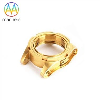
A sensor housing is not a container. It is a mechanical reference. The sensor must be held in a position where it physically touches the medium it is measuring, with no air gaps, no thermal barriers, and no structural flexibility. For a temperature probe, this means the probe tip must be pressed firmly against a machined brass pocket that is in direct contact with the water stream. For a pressure transducer, this means the diaphragm must be mounted on a rigid brass body that transmits the hydraulic force without distortion or vibration.
Brass is the ideal material for this role. Its thermal conductivity, around 120 W/m·K, is roughly twice that of stainless steel, meaning heat moves quickly from the water to the sensor tip. Its elastic modulus provides enough stiffness to hold a pressed-in sensor without creep over time. And its machinability allows the creation of precise pockets, threads, and sealing surfaces that would be impossible to achieve with casting or stamping.
From a structural-reliability perspective, the sensor housing must reject two types of interference: thermal and mechanical. Thermal interference comes from air gaps, which act as insulation and slow the sensor's response. Mechanical interference comes from vibration, which adds noise to the pressure signal. CNC machining eliminates both by creating a pocket with a defined interference fit, typically 0.01 to 0.03 mm, and a wall thickness that is thick enough to damp vibration but thin enough to allow fast thermal response. The result is a sensor that measures the coffee, not the machine.
The Equipment That Builds Honest Housings
Producing a precision sensor housing requires a combination of machining capabilities. Swiss-type lathes are essential for small-diameter components such as probe collars and thermowell necks, where the bar stock must be supported close to the cutting tool to prevent deflection. Three-plus-two axis milling is used for sensor pockets, wiring channels, and mounting flanges, allowing the part to be machined from multiple angles in a single setup. Precision thread grinding is used for pressure-port threads, whether NPT, BSP, or metric, ensuring that the thread pitch and profile are accurate enough to create a leak-free seal.
Coordinate measuring machines and vision systems are used to verify the pocket depth, the tip flatness, and the concentricity between the sensor pocket and the mounting thread. These inspections are essential because a sensor housing that looks correct may have a hidden deviation that only appears when the sensor is installed. Thermal simulation benches are used to correlate the sensor reading with a reference thermofilter, ensuring that the housing does not introduce a systematic offset. The cost of this equipment is significant, but the cost of a machine that brews inconsistently is far higher.
Practical Steps to a Sensor You Can Trust
The first step is to specify the pocket depth tolerance to plus or minus 0.02 millimeters. The sensor tip must bottom out flat against the brass, with no air gap and no spring compression. The second step is to use an interference fit on the probe collar, not just thread tightening. A threaded connection alone can loosen over time, creating a gap that degrades the thermal contact. An interference fit, where the collar is pressed into the pocket with a defined amount of interference, provides a permanent, vibration-resistant connection.
The third step is to isolate the electronic side from the wetted side with a defined seal groove. This prevents water or steam from reaching the sensor's electrical connections, which would cause corrosion and false readings. The fourth step is to machine a small thermal mass bridge between the water channel and the sensor pocket. This bridge, typically a thin wall of brass, allows heat to flow quickly from the water to the sensor tip, improving the response time without adding excessive thermal mass. The fifth step is to nickel-plate only the exterior of the housing, keeping the sensor contact face bare or gold-flashed. This prevents the plating from adding a thermal barrier between the sensor and the brass.
The final step is to calibrate each housing with the actual sensor model used in production. A housing that is optimized for one sensor may not perform the same with another, due to differences in probe length, tip geometry, and thermal mass. Calibration ensures that the housing and the sensor are matched, producing readings that are accurate and repeatable.
Real-World Experience from the Field
A prosumer espresso machine manufacturer in the United States was struggling with PID overshoot during warm-up. The temperature would climb to 95 degrees Celsius before settling back to the 93-degree setpoint, causing the first shot of the day to be over-extracted. The thermocouple was tested and found to be accurate, but the cast brass housing left an air gap behind the sensor tip. The manufacturer switched to CNC machined brass housings with a seated flat pocket and an interference-fit collar. The overshoot dropped to 0.3 degrees Celsius, and the machine held the setpoint within 0.2 degrees shot to shot.
A commercial service technician in Singapore encountered a recurring pressure-transducer error on a high-volume café machine. The readings oscillated by 0.4 bar, causing the controller to adjust the pump speed unnecessarily. The technician replaced the transducer, recalibrated the controller, and even replaced the pump, but the problem persisted. Finally, he removed the transducer tee and found that it was a thin-walled cast brass fitting that was vibrating with the pump. He replaced it with a CNC machined brass tee with a thicker wall and a shorter cantilever. The signal noise disappeared, and the pressure readings became stable.
The Housing Is the Measurement
Sensors do not create data. Housings create data. A sensor is a passive device that responds to its environment, but the environment is defined by the housing that surrounds it. If the housing has an air gap, the sensor reads the gap. If the housing vibrates, the sensor reads the vibration. If the housing is made of cast brass with inconsistent wall thickness, the sensor reads the inconsistency. CNC machined brass housings eliminate these variables, creating a stable, repeatable environment that allows the sensor to do its job.
The cost of a CNC brass sensor housing is higher than a cast or stamped one, but the improvement in measurement accuracy is worth it. A machine that measures accurately controls accurately. A machine that controls accurately brews consistently. A machine that brews consistently satisfies customers. The sensor housing is not a commodity fitting. It is a precision instrument that deserves the same engineering attention as the valve seats, the burr carriers, and the flow manifolds.
The Future of Sensor Integration
The next generation of sensor housings will be even more integrated. Brass housings will be machined with embedded RTD pockets, strain-gauge pressure ports, and RFID-tagged calibration data. The RFID tag will store the calibration curve for that specific housing and sensor pair, allowing the machine to self-calibrate when a new sensor is installed. The housing will also be designed for modular replacement, allowing a technician to swap a sensor and housing in minutes without draining the boiler or disassembling the group head.
These advances will be driven by the same forces that have driven the shift to CNC machining: the demand for consistency, reliability, and serviceability in coffee equipment. Buyers should treat sensor housings as precision instruments, not commodity fittings, and require thermal-response validation in their incoming inspection plan. The few extra dollars per housing will be repaid many times over in reduced service calls, improved coffee quality, and customer loyalty.