45° And 90° Reach Hidden Joints
Oct 15, 2026
Pain Point: Straight Tip Forces Redesign
Camera modules, hearing aids, sensor backsides, connector interiors-many bond points sit behind a wall. A straight needle hits the housing. Engineers redesign the product just to fit the dispensing tool. Wrong order of decisions.
Let me describe a real scenario. A camera module for a smartphone has a lens barrel that must be bonded to the sensor housing. The bond shelf is 3 mm deep inside the assembly, and the gap between the lens barrel and the housing is only 1.5 mm. A standard straight 30G tip is 12 mm long and 0.3 mm in outer diameter. It hits the lens barrel before reaching the shelf.
The engineer has three options: redesign the housing to provide more clearance, use a manual applicator, or find a custom bent tip. Redesigning the housing costs weeks and may compromise the optical alignment. A manual applicator is slow and inconsistent-the operator cannot control the dot size or placement with the same precision as a robot. The custom bent tip is the only viable option.
Manual application follows: slow, inconsistent, high smear. The operator applies adhesive with a handheld syringe, eyeballing the position and volume. The results vary from unit to unit. The yield is 85% at best. The rework is expensive because the adhesive is already cured.
Principle: Bend the Envelope, Not the Product
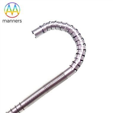
Needles can be lengthened, shortened, and bent to 45° or 90°. The key is keeping ID and bore quality through the bend.
A good bent nozzle uses formed stainless tubing with continuous treated bore. Fluid still sees a smooth path; only the external envelope changes. PP flexible needles bend more gently and protect fragile surfaces. Steel bent needles keep dimensional repeatability for robots.
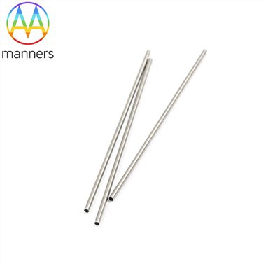
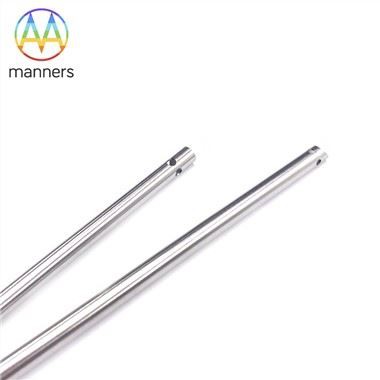
Let me explain the manufacturing process. A bent needle starts as a straight stainless tube. The tube is bent using a mandrel to prevent collapse. The bend radius is controlled to maintain the ID. The bore is then treated and polished to ensure a smooth flow path. The outlet is formed and deburred.
The bend does not compromise the fluid path if it is done correctly. The ID remains constant through the bend. The bore remains smooth. The fluid flows through the bend with minimal additional resistance. The key is the bend radius: too tight, and the bore collapses; too loose, and the needle is too long.
PP flexible needles are different. They are molded in a curved shape, not bent. The tube body has good flexibility, which protects the product from being scratched. The PP material can bend slightly under pressure, conforming to the surface.
Equipment Classification
- 45° steel bent nozzle: side wall, recessed ledge. The 45° bend allows access to bond points on the side of an assembly.
- 90° steel bent nozzle: bottom corner, hidden joint. The 90° bend allows access to bond points at the bottom of a cavity.
- PP flexible bent needle: fragile housing, scratch-sensitive part. The flexible body bends gently and protects the surface.
- Long bent nozzle: deep cavity with offset entry. The long reach allows dispensing into deep cavities at an angle.
- Custom 2D/3D bent nozzle: customer sample or CAD driven. The custom geometry is designed specifically for the application.
Operation Guide
Simulate collision envelope, not just deposit point. A 90° tip may clear the target but clip a wall on approach.
Keep bend radius as large as possible. Tight kinks raise flow resistance and trap filler.
Retract slowly in corners. Even a perfect bent tip smears if the robot yanks upward.
Let me give you a specific procedure. Before programming the robot, create a 3D model of the assembly and the bent nozzle. Simulate the robot path, checking clearance at every point. If the nozzle clips a wall, adjust the path or the bend angle.
During the run, monitor the deposit quality. If the dots are smeared, reduce the retract speed. If the dots are missing, check for a partial clog at the bend.
After the run, inspect the bend under magnification. A tight bend can develop a crack over time. If a crack appears, retire the nozzle.
Field Experience
A hearing-aid cell replaced manual UV application with 90° steel bent nozzles. Cycle time dropped from 11 s to 3.5 s; smear defects from 7% to <0.8%. The plant's process engineer noted that the bent nozzle also improved operator safety because the manual applicator was no longer needed.
A camera-module line reached a bond shelf others said "needs redesign." The fix was a bent nozzle, not a mechanical redesign. The line saved two weeks of engineering time and avoided the risk of compromising optical alignment.
A medical device manufacturer used a 45° bent nozzle to bond a component inside a narrow housing. The previous process required manual application, which was inconsistent. The bent nozzle enabled robotic dispensing, improving yield from 85% to 98%.
Summary
Do not redesign the product to fit the tip. Form the tip to fit the product.
The cost of a redesign is not just the engineering time. It is the risk of introducing new defects, the delay in production, and the opportunity cost of not shipping. A bent nozzle eliminates all of these costs.
Outlook
CAD-to-needle services will normalize: upload assembly model, receive validated bent-nozzle drawing in 24–48 h.
Manufacturers will offer simulation services that predict the flow characteristics of a bent nozzle before physical prototyping. The engineer will see the pressure drop, the velocity profile, and the deposit shape on screen.
Expect to see a library of standard bend angles: 15°, 30°, 45°, 60°, 90°. These will be available as standard options, reducing the cost and lead time of custom bent nozzles.