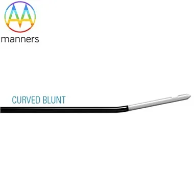
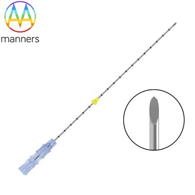
Taper For Micro Dots, 0.1 Mm ID
Oct 15, 2026
Pain Point: Sub-0.3 mm ID Looks Impossible Until It Isn't
Reagent makers want 0.05 µL. MEMS makers want a 0.2 mm ribbon. Lens makers want an 80 µm glue fillet. A constant bore at 0.1 mm ID clogs from a single dust fiber. People blame the pump, the barrel, the valve, the moon.
Let me describe a real production scenario. A diagnostic strip manufacturer is dispensing an enzyme reagent at 0.05 µL per dot. The needle has a 0.1 mm ID. The operator installs the needle and starts the dispenser. The first 10 dots are perfect. Then dot 11 is missing. The operator checks the pressure-it is stable. The operator checks the barrel-there is plenty of fluid. The operator replaces the needle. The dots return to normal.
The operator examines the old needle under a microscope. There is a single dust fiber, 5 microns in diameter, wedged in the bore. The fiber blocked the flow. The operator realizes that the needle is not the problem-the fluid filtration is.
Now consider a MEMS gyroscope manufacturer. They need to deposit a 0.2 mm wide ribbon of adhesive onto a silicon substrate. The gap between the substrate and the bonding tool is only 0.3 mm. A standard 30G needle has an outer diameter of 0.31 mm-it does not fit. A 32G needle has an outer diameter of 0.23 mm-it fits, but the bore is 0.11 mm, and the adhesive has 10 µm filler particles. The filler particles bridge the bore and clog the needle within 50 shots.
The operator tries to reduce the pressure. The dots become inconsistent. The operator tries to increase the pressure. The filler packs harder. The operator replaces the needle every 20 minutes. The line loses 30 minutes of production per hour.
The same story repeats in lens bonding, medical device assembly, and semiconductor packaging. The problem is not the needle-it is the mismatch between the bore diameter, the filler size, and the fluid path geometry.
Principle: Taper Creates a Funnel, Not a Straw
At 0.1–0.3 mm ID, the entrance geometry dominates. A tapered lead-in pre-centers fluid, reduces entrance loss, lowers shear at the wall, and gives filler a "runway" instead of a wall.
Let me explain the entrance loss in detail. When fluid enters a constant-bore needle, it must contract from the barrel diameter to the bore diameter. The contraction creates a pressure drop and turbulence. The turbulence creates eddies at the entrance, where filler particles can collect and bridge. In a tapered needle, the contraction is gradual. The pressure drop is lower, and the turbulence is reduced. The fluid flows more smoothly, and the filler particles are carried forward by the flow.
The taper also affects the velocity profile. In a constant-bore needle, the velocity profile is parabolic: the center moves fast, the edges move slow. The slow-moving boundary layer creates shear stress, which generates heat and increases viscosity. In a tapered needle, the gradual narrowing flattens the velocity profile. The shear stress is lower, and the fluid moves as a more coherent column.
Micro dispensing is 80% fluid-path geometry and 20% pressure. The taper is the geometry.
ISO13485 matters here because 0.1 mm ID means one particle = one defect. You cannot "visually inspect" a 0.12 mm lumen with the naked eye. You validate surface finish, cleaner, and flow statistics. The surface finish of the bore is critical: a rough bore has microscopic peaks and valleys where particles can lodge. An electropolished bore with Ra 0.1–0.2 µm has no valleys. The particles cannot lodge, and the bore is easier to clean.
Equipment Classification
The 0.1–0.2 mm ID ultra-fine taper is used for reagent, biochem, and MEMS applications. The ultra-fine taper provides precise control for micro-dosing. The 0.25–0.4 mm ID fine taper is used for UV fillet and optical bond applications. The fine taper provides a balance of precision and flow. The 0.5–0.8 mm ID taper is used for micro-potte, phosphor dot, and small gasket applications. The taper provides a controlled flow for slightly larger deposits.
The custom drawn taper is designed for customer 2D/3D drawings with non-standard lead-in angles. The custom taper is designed for a specific application. The taper + non-stick liner is used for CA glue and primer micro dose applications. The liner prevents flash-curing on the bore wall.
Each class has a different flow characteristic. The ultra-fine taper has the highest pressure drop and the most precise control. The fine taper has a moderate pressure drop and a good balance of precision and flow. The 0.5–0.8 mm taper has the lowest pressure drop and the highest flow rate. The custom taper is optimized for the specific application. The taper + liner adds a non-stick surface that prevents flash-curing.
Operation Guide
Filter fluid: 5–25 µm depending on ID. The filter removes particles that could clog the bore. For a 0.1 mm ID, a 5 µm filter is recommended. For a 0.3 mm ID, a 25 µm filter may be sufficient.
De-aerate; micro bores hate air. Air bubbles in the bore cause inconsistent dots. The air can also compress, causing a delay between the valve opening and the fluid flow.
Pre-wet bore with compatible thinner if house allows. The pre-wet improves the initial flow. The thinner fills the bore and prevents the first shot from being starved.
Dispense by time + pressure, then convert to volume control. Volume control is more accurate than time + pressure. The volume control system measures the actual deposit and adjusts the pressure and time accordingly.
Clean after every job, not weekly. The residue builds up quickly in a fine bore. A single missed cleaning can cause a clog that ruins the next run.
Requalify with ≥10 weighed shots; reject if one dot outliers. The weighed shots prove the bore is functionally clean. If one dot is an outlier, the bore is not clean enough for production.
Let me give you a specific procedure. Before each run, inspect the needle under 40× magnification. Check the outlet for burrs or damage. Install the needle and prime 10 shots onto a waste substrate. Weigh each shot on a precision balance. If the 10 shots vary by more than 3%, stop and investigate. Check for air in the barrel, contamination in the bore, or a loose hub.
During the run, monitor the dot weight every 50 shots. If the dot weight drifts, stop and clean the needle. Do not adjust the pressure to compensate-the drift is a sign of bore fouling.
After the run, flush the needle immediately. Use the forward-flush sequence: glue out, cleaner in, dispense cleaner, ultrasonic jolt, rinse, dry. Store the needle in a dust-free container.
Field Experience
A IVD strip filler running 0.15 mm ID tapered steel nozzles cut dot-CV from 9.8% to 3.1% after adding fluid filtration + end-of-job forward flush + 3-min US. Audit passed because each needle had a bore micrograph and cleaner lot. The process engineer noted that the filtration was the most important improvement. The 5 µm filter removed the dust fibers that caused the intermittent clogs.
A MEMS house bonding with 0.2 mm ID taper eliminated "first-dot fat" by priming into a waste pad and logging shot #1 mass separately. The process engineer noted that the first-dot fat was caused by the fluid column settling in the bore overnight. The prime shot removed the settled fluid and restored the correct deposit.
A lens manufacturer using a 0.12 mm ID taper for optical adhesive found that the taper reduced stringing. The gradual narrowing created a cleaner meniscus break, so the fluid did not pull a thread when the valve closed.
Summary
Micro dispensing is not magic pressure. It is a clean funnel, a clean fluid, and a clean proof. The taper manages the flow, the filtration manages the particles, and the validation proves the process.
The cost of a clogged micro needle is not just the needle. It is the missed dot, the failed product, and the investigation time. A taper that manages flow, combined with a filtration system, eliminates all of these costs.
Outlook
0.1 mm ID nozzles will ship with particle-count certificates and "max allowable filler size." The spec sheet will read like a fluidics component, not a hardware item. Manufacturers will publish flow curves for each micro taper, showing the relationship between pressure and flow rate. Process engineers will use these curves to select the optimal nozzle and pressure setting.
Expect to see "micro-dispensing validation kits" that include a flow test stand, a particle counter, and a bore inspection microscope. The future of micro dispensing is not just a needle-it is a validated process.