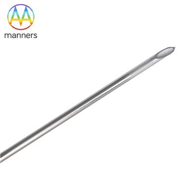
Micro Shaft
Sep 16, 2026
Below 0.4 millimeters in diameter, the rules of guidewire engineering change dramatically. The pain point is that processes which work flawlessly at macro scale become sources of failure at micro scale. A 0.012 mm kerf, impressive on a 3 mm tube, becomes a structural event on a 0.20 mm tube-removing a significant fraction of the wall cross-section. A 5-micron burr that would be invisible on a larger device can alter trackability, increase friction, and damage delicate neurovascular tissue. Micro hypotubes fail not because the laser lacks power but because the entire process chain-from tube straightness to clamping force, from heat dissipation to handling-must be controlled at a level far beyond conventional manufacturing. The challenge is to produce parts that are not merely small but consistently functional, safe, and reliable across thousands of units.
At micro scale, the behavior of a hypotube is dominated by ratios: kerf-to-diameter, wall-to-diameter, slot-length-to-circumference. A 0.20 mm OD tube with 0.03 mm wall has only 60 microns across the wall pair. Removing a 12-micron kerf changes the local load path by double-digit percentages. Micro-trackability depends on low bending stiffness at the tip, adequate torsional stiffness for rotation, enough column strength to advance, an atraumatic tip shape, and a lubricious yet durable coating. Laser cutting must be non-contact and thermally gentle. Ultrashort pulse lasers (femtosecond or picosecond) help because ablation dominates over thermal conduction, minimizing heat-affected zone. But even with the best laser, micro parts require internal mandrel support during cutting, vibration-free stages, cleanroom transfer, and non-contact metrology. The margin for error is measured in microns, and the cost of failure is measured in scrapped batches and delayed product launches.
The equipment for micro shaft production includes femtosecond or picosecond lasers, rotary vacuum chucks to prevent deformation, sub-micron vision alignment systems, confocal or OCT metrology for non-contact measurement, anti-static formed trays for damage-free handling, cleanroom ultrasonic cleaning to remove particulate without cavitation damage, and micro tip-forming and welding stations. Materials include thin-wall 304 or 316L stainless steel for cost-effective micro access, Nitinol for neuro and retrieval applications, platinum or tungsten for radiopaque tips, and hybrid polymer liners for lubricity. Each material demands specific laser parameters and handling protocols, as the thermal and mechanical properties vary significantly at micro scale.
Practical micro shaft design starts with tube straightness-if the raw tube is not straight, no laser can cut it accurately. Internal mandrel support prevents collapse during cutting. Laser parameters should use small pulse energy, high repetition rate, and minimal heat input. Kerf measurement requires 500x magnification minimum. Electropolishing must be tightly controlled: micro walls disappear quickly under over-etching. Coating should be applied distal-only if slots must remain open for flexibility. Packaging must be formed, never loose in a carton, as micro parts tangle and scratch easily. Testing should occur in curved micro-phantoms with resistance, not straight jigs that fail to replicate clinical conditions. The entire process chain, from incoming material to final inspection, must be designed for micro scale, with every step validated and controlled.
Real-world experience demonstrates that micro manufacturing is as much about discipline as technology. One neuro micro-guidewire program suffered 22% scrap from "mystery bends." The laser was fine. The ultrasonic cleaner was deforming 0.02 mm walls through cavitation. Switching to low-power swept-frequency cleaning with deionized rinse and nitrogen dry cut scrap in half. Another program improved yield not by changing the laser but by changing gloves and tray material-at 0.25 mm diameter, the factory floor is part of the device. These examples show that micro shafts expose weaknesses in the entire quality system, from incoming inspection to final packaging.
Micro shafts are not simply smaller versions of larger tubes-they are a different engineering domain. The physics of heat, stress, and surface interaction change at small scale, and the process chain must evolve accordingly. Success requires a factory environment that approaches semiconductor cleanroom standards, with rigorous control of every variable. The reward is a device that can navigate the most challenging anatomies, enabling procedures that were once impossible.
The future of micro shafts will see sub-0.15 mm hypotubes with embedded optical fibers for illumination and sensing, sensorized tips that provide force feedback, and patient-specific designs generated from pre-operative imaging. Manufacturing will move toward fully automated, lights-out production in ISO Class 7 or cleaner environments. As endovascular procedures extend into smaller vessels, the demand for micro hypotubes will grow, driving innovation in laser technology, materials, and process control. The companies that master micro scale will define the next generation of interventional devices.